Movement No. 42 is the first of two mechanisms (Movements 42 and 43) demonstrating different gear types capable of transmitting rotary motion between two shafts that are arranged obliquely to one another — that is, shafts that are neither parallel nor intersecting, but skewed in three-dimensional space. This geometric arrangement is known as a skew shaft configuration, and it presents a unique challenge to gear designers: the axes of the two shafts do not share a common plane, meaning conventional spur gears (which require parallel shafts) and bevel gears (which require intersecting shafts) cannot be used. Movement No. 42 addresses this challenge with crossed helical gears — also known as screw gears or skew gears. These are essentially two helical gears with helix angles chosen such that when mounted on their respective skew shafts, their helical tooth surfaces mesh smoothly at the crossing point. Unlike spur or bevel gears where teeth engage along a line, crossed helical gears make point contact between their tooth surfaces — the two curved helical tooth profiles touch at a single point at any given instant, and this contact point moves across the tooth surface as the gears rotate. This point contact nature means that crossed helical gears have a lower load capacity compared to line-contact gears of the same size, and they require good lubrication to manage the sliding friction at the contact point. However, they offer the significant advantage of being able to connect skew shafts at virtually any angle and any shaft offset distance — a geometric versatility that no other simple gear type can match. Crossed helical gears are widely used in low-to-moderate load applications such as speedometer drives, instrument mechanisms, and small machinery where non-parallel, non-intersecting shafts must be connected.
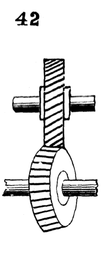
42 and 43. Different kinds of gears for transmitting rotary motion from one shaft to another arranged obliquely thereto.